Showing posts sorted by date for query green room. Sort by relevance Show all posts

Monday, November 26, 2018

repairing the fenders

December 2015: now this is where things went off at a tangent...again! Most of the bodywork on this project was done back in 2011 when I was custodian of a very large garage in Hayward known as the green room. The body shell and most of the parts that will someday be repainted body color were stripped down, repaired, primed with PPG epoxy and treated with body filler (rinse & repeat etc.). So far so good, but when the time came to move garage the trunk lid, hood and both fenders were still in “pre-restored” condition.

And that’s how they remained, for a number of reasons, but mainly because the garage I moved to was too small to set up a welder and a paint gun. Fast forward to the Christmas/New Year holiday at the end of 2015 and I had to decide whether I was going to put a pair of horrible rusty fenders back on my nice clean car....or do something else?

The something else came down to a straight choice between stopping the rebuild to restore the fenders, or replacing them with reproduction parts and getting back on with the rest of the assembly asap. I must admit to a lot of back and forth on this. While Dynacorn™ reproduction fenders are available for less than $150 each through Tony at RPS in Hayward, I was really concerned that they would not line up properly. But then my original fenders were not in the best of shape either and I knew they would take a lot of precious time to restore. Ultimately I decided on restoration of the originals.

Over the Christmas holidays at the end of 2015 I took the fenders off the car and transported them the three blocks back to the shed I built the summer before last. Here is the "before" photo:


I broke out the wire wheel and ground off all the accessible rust and grot from the inside of the passenger fender.


The only seriously damaged area was in the bottom corner at the rear of the fender. This area was cut out with the screaming wheel of death and replaced with new metal using the MIG welder than had been stuck inside a box for the prior four years.


The repaired area was the filled with Bondo™ and sanded, more than once.


A similar repair was made at the inside.


The bare metal was painted with rust converter which was sprayed in the areas I couldn’t get to with a brush. Lovely jubbly.


The unprotected section of the inner side of the fender was treated with a think layer of rubberized bedliner


All these steps were repeated with the driver side fender over the following few days. My shed was too small to work on more than one at a time. When they were both completed, I broke out the replacement fender ornaments I've had in storage for...well years, obviously. The engine has been upgraded from the 200 cid straight six, to the 351 cid Windsor, and I wanted to mark that with the right "351W" fender badges, even though this engine was not available in the Mustang in 1968. Of the four pegs which secure the new ornament, three are in the same place as the originals so I had to drill one extra hole in the fender....better to do this now than after paint!


The original splash guards were in awful shape so I bought replacement parts from NPD and assembled them in my shed.


I installed the replacement splash guards back at the garage:

One piece goes inside the front of the fender...

...and the other attaches to the car body

I also attached the front fender caps which were refurbished and spray painted with epoxy primer way back when.
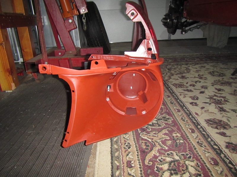

Finally the fenders were hung on the car and the headlight buckets installed.  Happy New Year 2016!

Tuesday, November 20, 2018

engine parts and cable clutch

Fall 2015: the engine was in, the water and fuel pumps were installed, and the brake system was complete.

Not too shabby

Next up: the radiator. This how it looked in about 2012 when I acquired it from one of my mates in BAMA. I think it was painted either at the last garage or at the Green Room along with most of the other black engine parts.


I have a custom overflow bottle which I painted at the same time along with the side panels which help attach the radiator to the car.


This is how the radiator looked after installation. I had to take it back out later on to do the wiring... 


I may have mentioned earlier that step-by-step photos just don't exist for much of this period, and anyway, most of it was just bolting on shinny new parts that had been sitting in their boxes for a year or more.

bolted on the mini starter

mounted the electronic ignition box at the driver side fender apron 

harmonic balancer with 4-bolt pattern 

one of two inline fuel filters

I had decided to replace the original clutch linkage with a cable. Thankfully for a novice like me, the guys at Modern Driveline have produced a kit which makes it very easy to marry up the cable with the original zinc-plated clutch pedal and my modern Tremec T5 transmission. I also got a replacement speedometer cable at the same time, and I had the gears setup for the 3.40:1 differential.


Installing the kit was easy. The only issue was that I had to remove the master cylinder and disconnect the push rod before I could install the supporting plate. Installing the speedometer cable was a bit more involved. The first one I tried was about a foot too long, so I had to get a replacement, and I had to take the instrument cluster out twice. This was all too tedious to photograph.


This is how the distribution block and proportioning valve looked after the master cylinder was re-installed and the brake system bled....again....


I used a welding rod to figure out the ideal shifter stick position, and then ordered the nearest I could get from Summit.


This is how it looked with my custom handle installed ;)

Sunday, January 25, 2015

putting the brakes on

I finally got back to some mechanical work at the beginning of October. Longer term followers of this blog might recall that I had a few problems with my front brake system. I tossed away the six cylinder drum components and replaced them with an old Granada set up that I acquired through the BAMA mafia. Later I found that the the hub size on the replacement Granada rotors was too big for my wheels. This led to me transferring the car from the Green Room to my garage in Emeryville with a pair of Ranger wheels on the front. That was in April 2012, and that's exactly where those wheels stayed for the next two and a half years.

Ranger wheels: not very sexy.

I always planned to take the replacement Granada rotors and have the hubs turned down so they fit the wheels. But I struggled to find a machine shop that could do this for me. Later I talked to Mike Maier about the inadequacies of the Granada swap. A couple of months after that I was in Reno for Hot August Nights when I found myself being dragged into the "Big Boys Toys" exhibition hall, and slowly sucked towards the Stainless Steel Brake Co stand. A few minutes after that one of the Summit Racing guys was passing my credit card though an exceedingly hot swiping machine. It must have been hot, because the credit card was melting when I got it back!! A week or so after that some very heavy SSBC boxes showed up at the house. Around this time I also ordered the roller spring perches from Opentracker Racing that we've all heard so much about.

Roller perch (left) and static stock option (right)

After tearing off the Granada spindles (and all the related parts which I spent time restoring...sigh...) it was straight forward to install the SSBC spindles, dust shields and rotors. It's probably fair to say that the SSBC system is overkill for this car, but I just decided not to make any ecconomies with the brakes.


Getting the caliper brackets and calipers assembled and installed correctly was a bit more traumatic, but I eventually got there. Then I wiggled the car away from the garage wall and did the same to the driver side.

Wheels fit now..!

The SSBC brake system comes with a new master cylinder (MC), flexible lines, and all the hardware. It also includes some short sections of hard brake lines, because the setup requires several modifications to the stock lines. Plus you have to install a proportioning valve (PV) that wasn't needed with the original all-drum system.

One of the reasons for working on the brake system now (and the fuel system next) is that I wanted to get all the lines installed before I put the engine and transmission back in. So I ordered up a set of stock brake lines from NPD and set about attaching them to the chassis. The rear brake lines went in just so, and I made finger-tight connections to the wheel cylinders. Nice. The central line at the transmission tunnel and firewall and the connections at the front discs were also pretty easy. I was able to utilize most of my shinny zinc plated hardware with the SSBC brackets.


I bolted up the MC and connected the brake pedals and the piston. You are supposed to bench bleed the MC before installing it in the car, but I didn't because I only bothered to read the instructions afterwards. At this stage I was a little bit more concerned about where to mount the PV and how to get the lines anywhere near to the MC, never mind connect flawlessly.


Of course there was no distribution block included with the SSBC kit, so I had to dig out the original and refurbish it. That's one more time that keeping EVERYTHING from the tear down has saved me.

That's better

I guess it also goes without saying that the brake lines that come in the SSBC kit have completely different connectors to the ones that come from NPD. And they're not quite the right shape, and anyway I've never had to make custom brake lines before, so why not now? Well the answer to that questions is probably "because it's a tedious PITA!" First I had to invest in a pipe bender, and then a flaring tool, and then in some extra brake lines from the local parts store, and then some more spare brakes lines...and...well when it was all done it looked like this:


Now to me it wasn't too bad for a first time, but I know for a fact that some of the flanges are not right, and that a lot of the bends look amateurish. For now though, it's a start.

To be continued...

Friday, June 27, 2014

waiting for the heads

OMG It's been FOUR months! There have been a number of "down" periods on this project - and many more periods of intensive work - but that last few months have been somewhere in-between: short bursts of work punctuated by longer periods of...nothing. Oh well...

At the end of my last post I found myself unexpectedly in need of a valve job and without a machine shop. There are ways to find these things I guess (like the interwebs), but, as mentioned countless times already in this blog, I like to start by asking the guys in BAMA when I need something. What was unusual about this time around was that instead of finding a machine shop, I found a specialist head builder that was already in the club! In fact, the owner of Heads by Steve in San Ramon has decades of experience building heads, many have which have been run in NASCAR teams.

So I cut a deal with Steve to do the valve job, install 7/16 inch screw-in studs, and port match the heads to the gaskets and the intake manifold. When the heads came back a few weeks later they were just....well....immaculate.


And the ports were just so smooth, I could see the increase in power!


While the heads were away, I was marooned at home, surround by lots of boxes filled with shinny new engine parts. This spurred me on to crank through some of the half- and three-quarter-finished mini projects I'd previously abandoned. The first one was the tail lights and trunk wiring harness, which I couldn't face after the painful process I endured below the dash. The tail light buckets were refurbed, and painted brake gray (outside) and brilliant white (inside) back in the Green Room days.


The concave tail lights were the feature that first attracted me to the 67/68 cars in the first place. I acquired a bunch of extra OEM trim pieces from my buddies up the Street at Mostly Mustangs and picked out the best six pieces. I replaced the rubber pads, although attempting the glue the new pads to the trim pieces with weatherstrip adhesive was an abject failure. The studs and nuts were zinc plated way back when...


The tail light connectors were, of course, not included in the Pathetic Painless wiring harness, so I adapted the originals. I did the same with the back up lights. And the fuel tank sender connector....and most of the stuff in the engine compartment too no doubt. The Pitiful Painless harness was actually too short to reach both tail lights, so I did a bunch of chopping and joining of wires that I would rather not have had to do. In the middle I ran out of the wire connectors supplied in the P...p...p...FUCKING AWFUL Painless kit, and had to run to Home Depot. Grrrr!!


I also completed installing the Dynamat in the passenger compartment and taped the joints. Long-overdue!


Next time: Engine Rebuild. I mean it this time!!